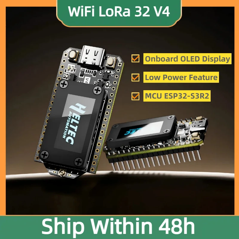
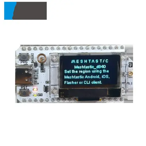
Heltec Wifi LoRa 32 V4 Development Board ESP32 SX1262 GPS 0.96 inch OLED Meshtastic Solar Powered WiFi BLE Low Power For Arduino IoT
Heltec Wifi LoRa 32 V4 Development Board ESP32 SX1262 GPS 0.96 inch OLED Meshtastic Solar Powered WiFi BLE Low Power For Arduino IoT - Details and Specifications
Specifications
| Dimensions | 51.7 * 25.4* 10.7mm |
|---|---|
| Origin | China |
| Accessory Type | USB To DC Cable |
| Typical Application Fields | Internet of Things (IoT) |
| Compatible With | Lora 32 V4 |
| Master Chip | ESP32-S3R2 |
| LoRa Node Chip | SX-1262 |
| Frequency | 470~510MHz, 863~928MHz |
| Max. TX Power | 21±1dBm, 27±1 dBm |
| Max. Receiving Sensitivity | -137 dBm |
| Wi Fi | 802.11 b/g/n, up to 150Mbps |
|---|---|
| Bluetooth | Bluetooth LE, Bluetooth 5, Bluetooth mesh |
| OLED | SSD1315(0.96Inch, 128*64 resolution) |
| Power Supply | 5V@USB, 3.3-4.2V@Battery |
| Operating Temperature | -40~85℃(OLED operating temperature: -40~ 70°C) |
| Package Length | 9 |
| Package Width | 6 |
| Package Height | 5 |
| Gross Weight | 0.055 |
Summary
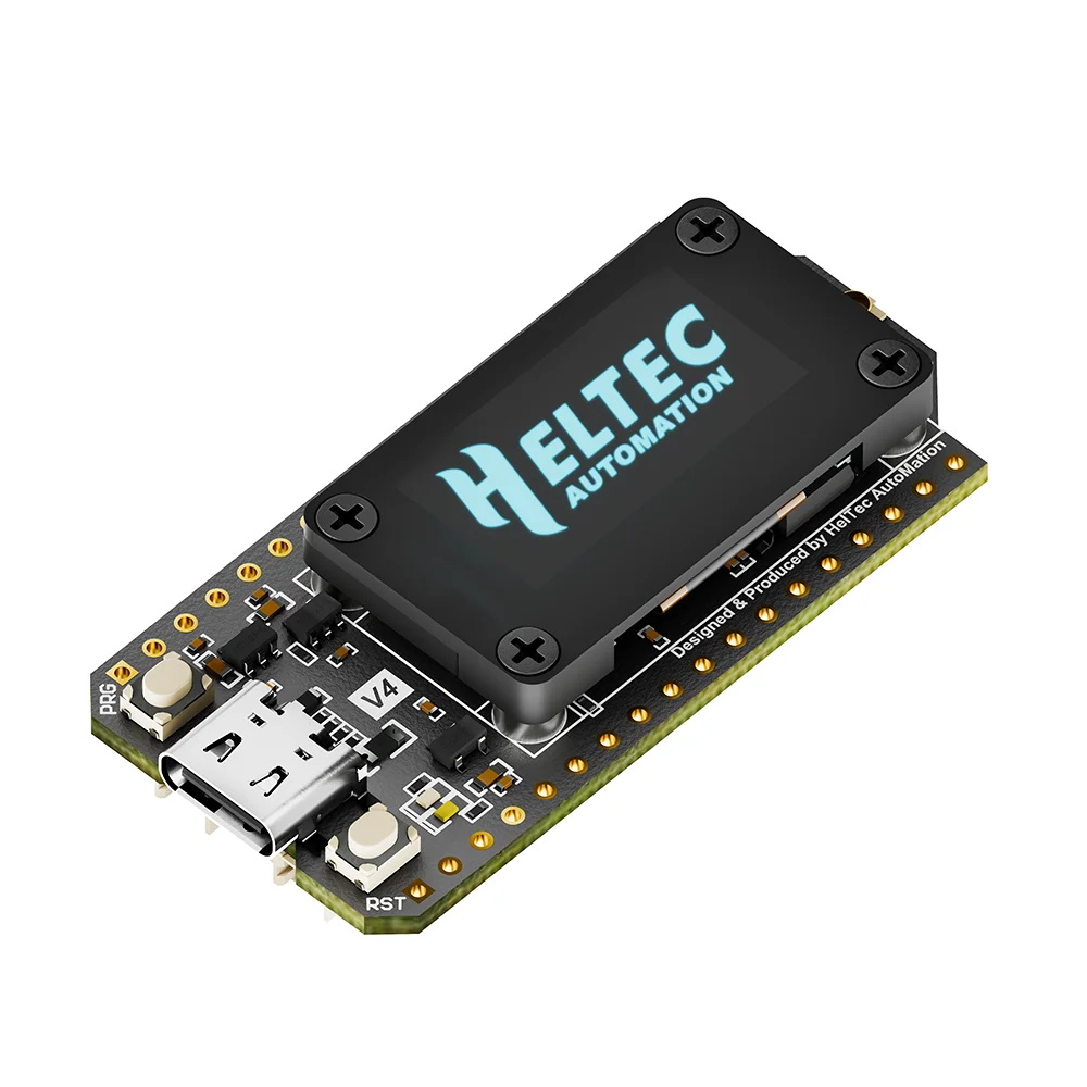
- Heltec WiFi LoRa 32 V4 is a fully upgraded version of the classic LoRa development board. Since its initial launch in 2017, this product series has been highly favored by developers and makers.
- Building upon the powerful features of its predecessors, the V4 version introduces comprehensive optimizations in transmit power, power management, expandability, and other hardware designs.
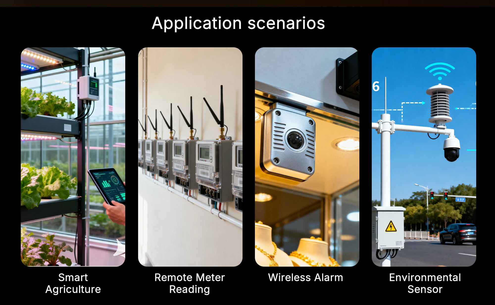
- It is suitable for various IoT applications such as smart cities, agricultural monitoring, smart homes, industrial control, security systems, and wireless meter reading, providing developers with a more efficient and flexible development experience.
More detailed WiFi LoRa 32(V4) introduction - Scan and watch for more on YouTube:
https://youtu.be/JRidd85Rm5U?si=RMP22rGAFhoh5dAM
Main Features
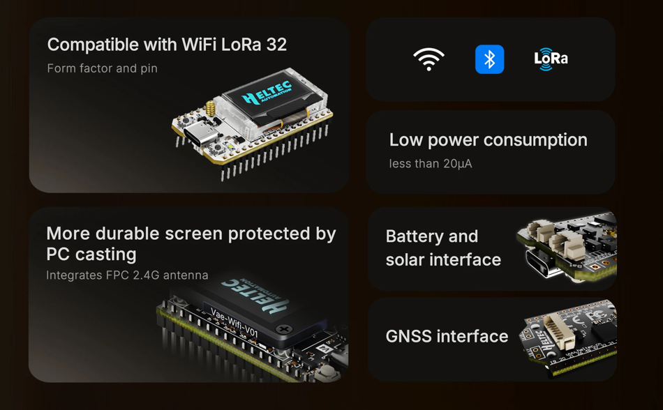
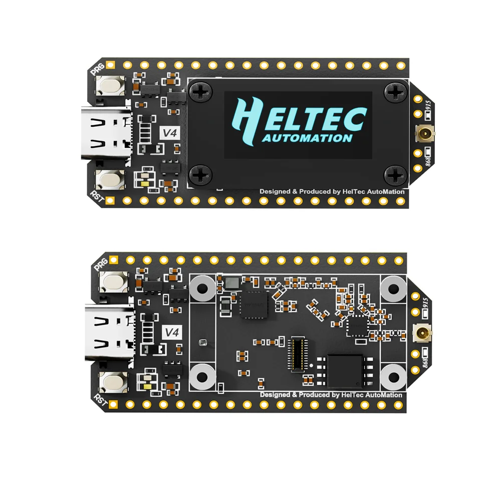
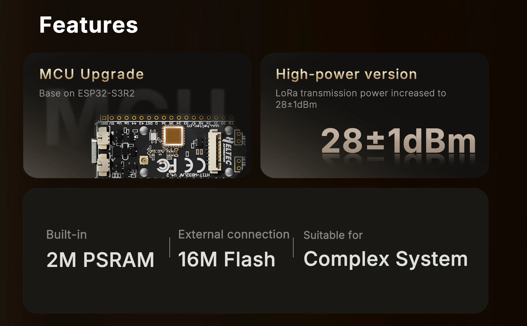
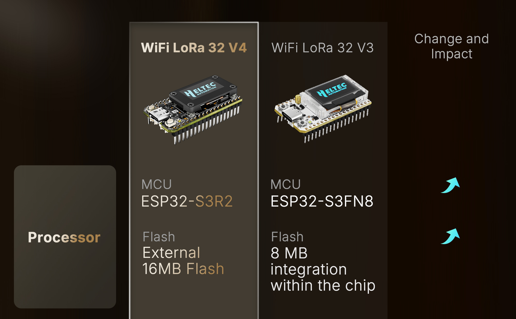
- Based on ESP32-S3R2 and SX1262, supports Wi-Fi b/g/n, BLE, and LoRa communication.
- 2MB PSRAM and 16MB external Flash, more suitable for UI and complex systems.
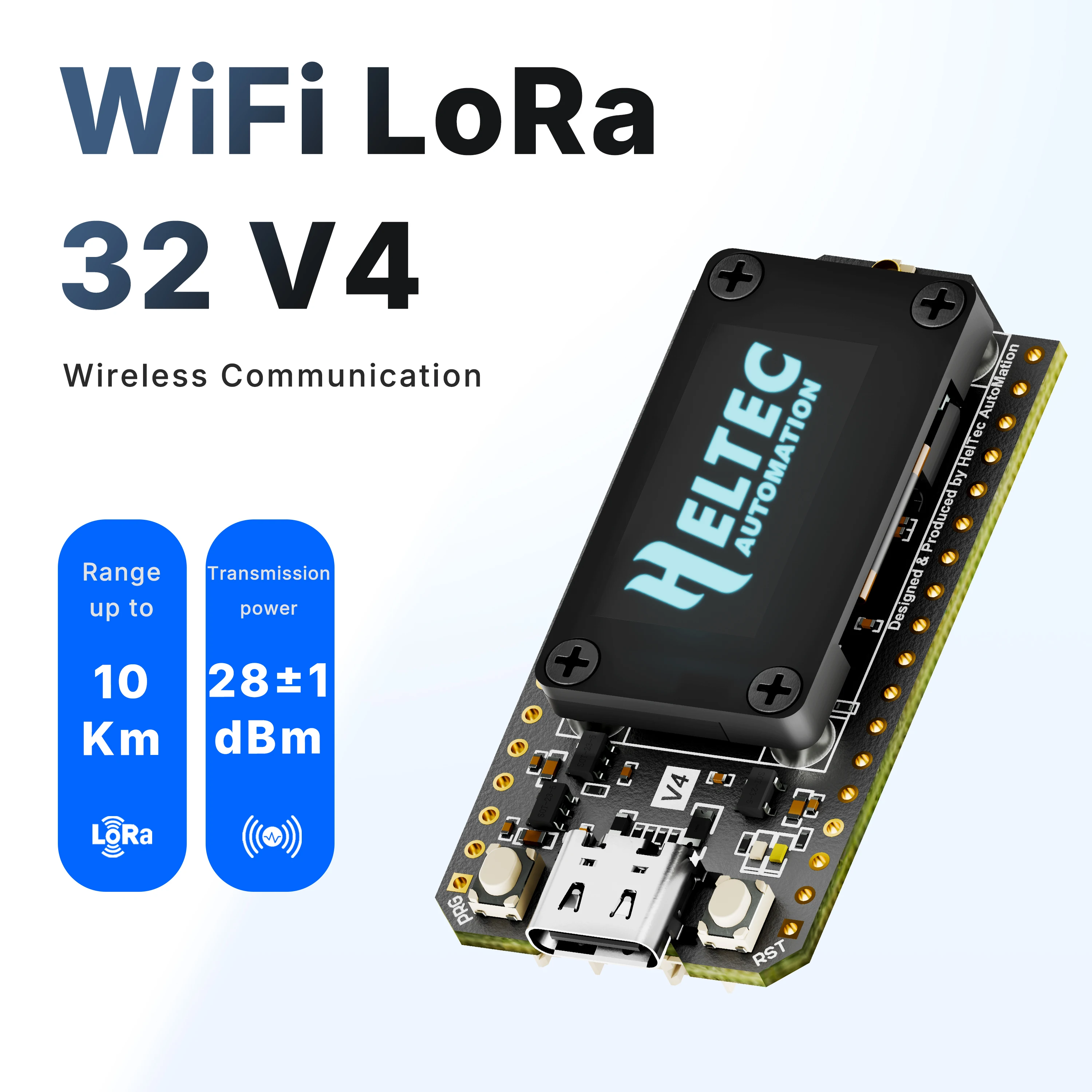
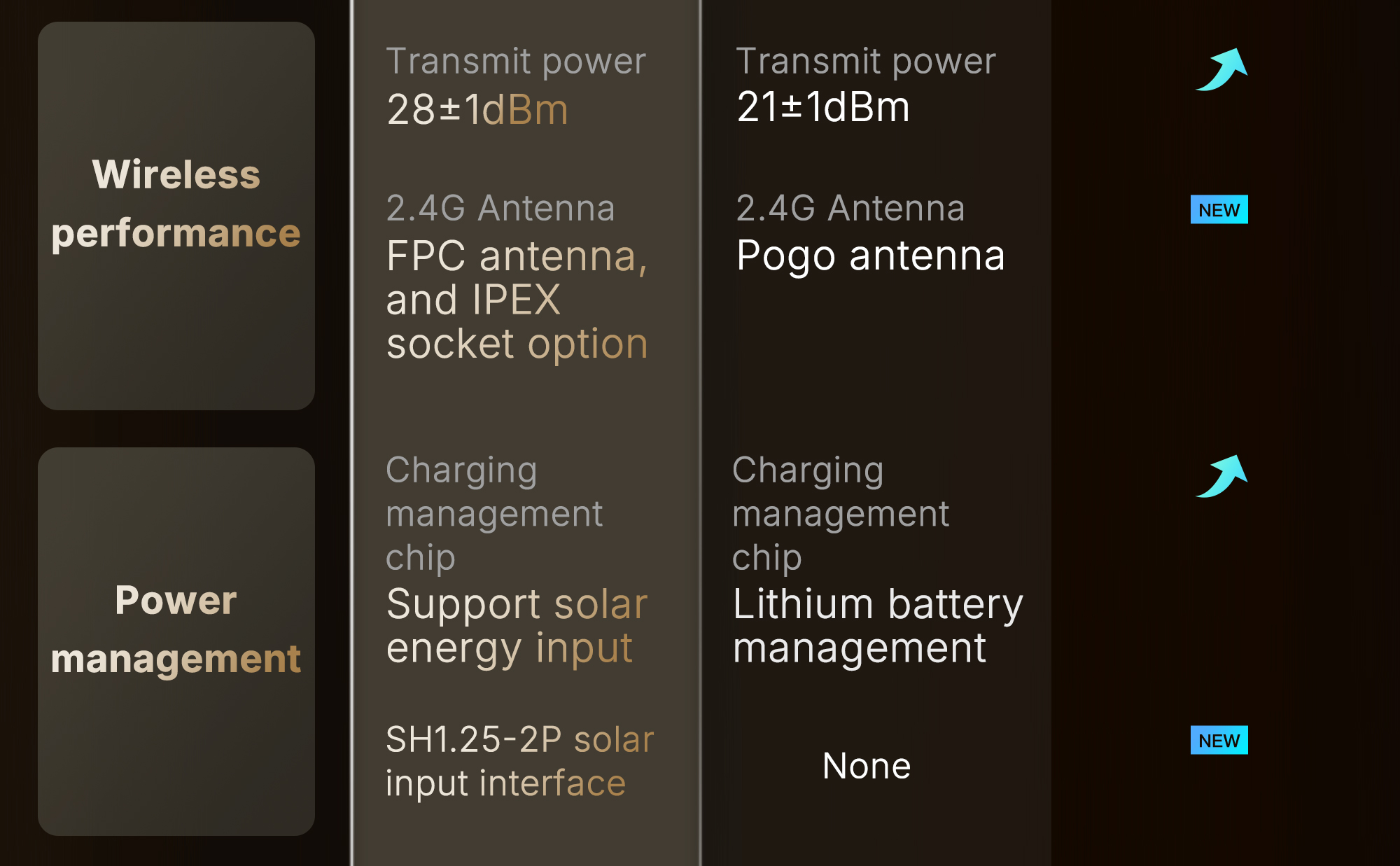
- High-power version with LoRa transmission power increased to 27 ± 1 dBm.
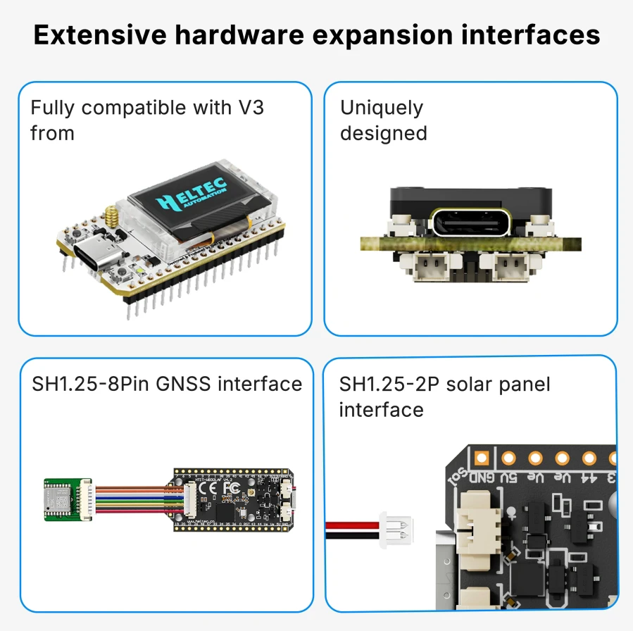
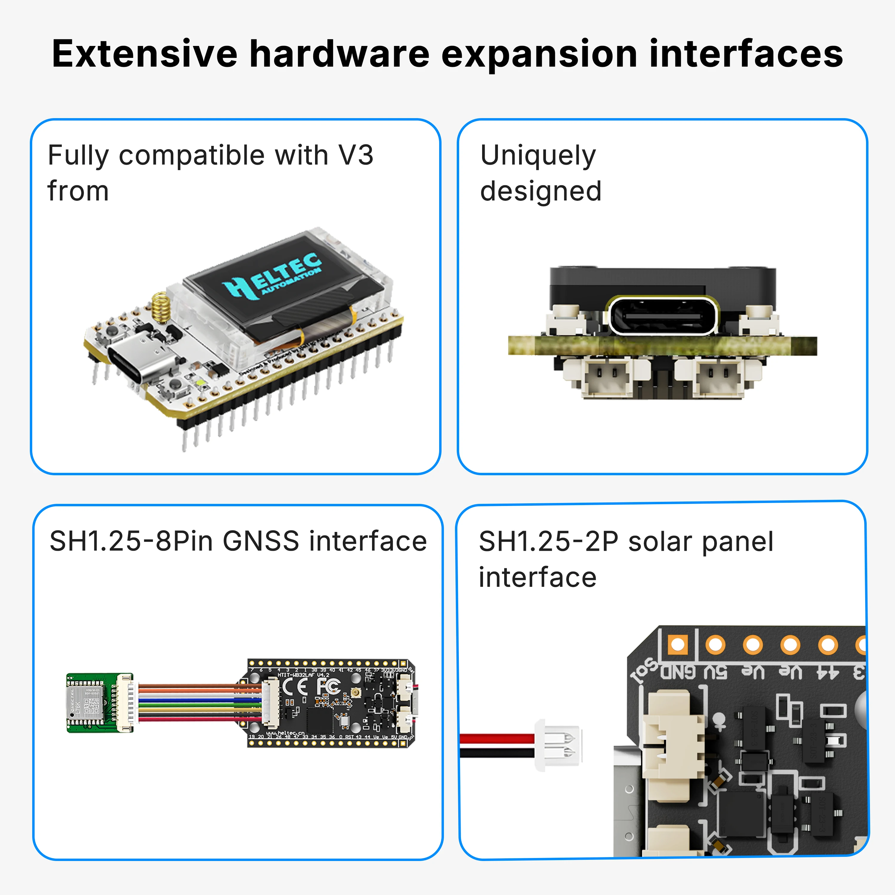
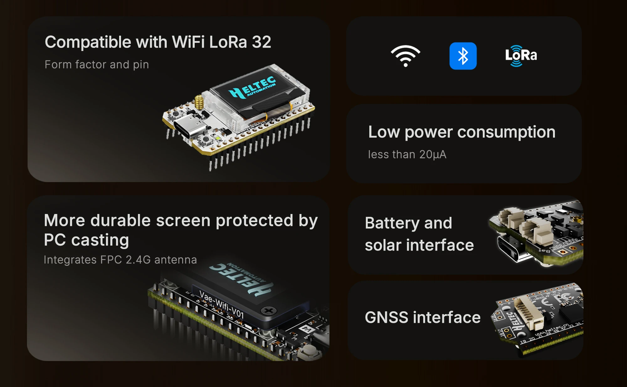
- Form factor and pin compatibility with WiFi LoRa 32 V3.
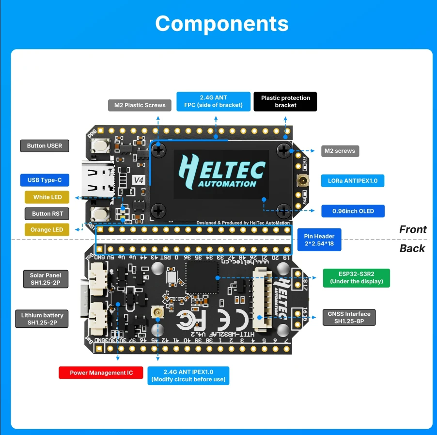
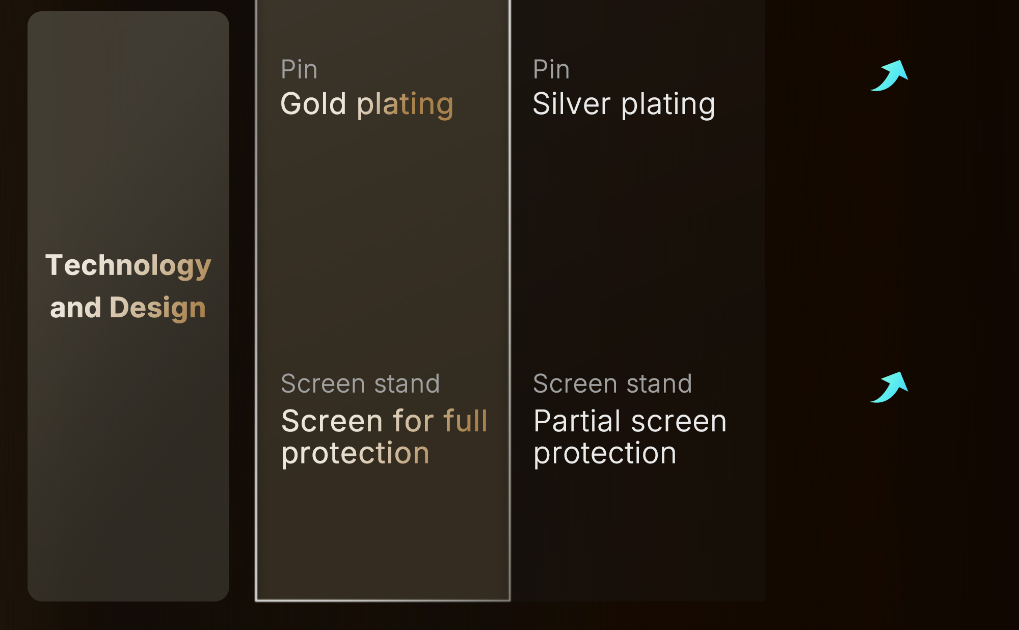
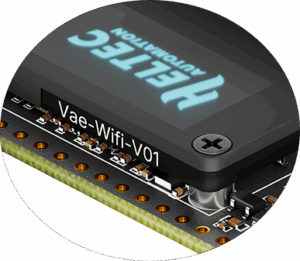
- PC casing protects the screen and integrates an FPC 2.4G antenna.
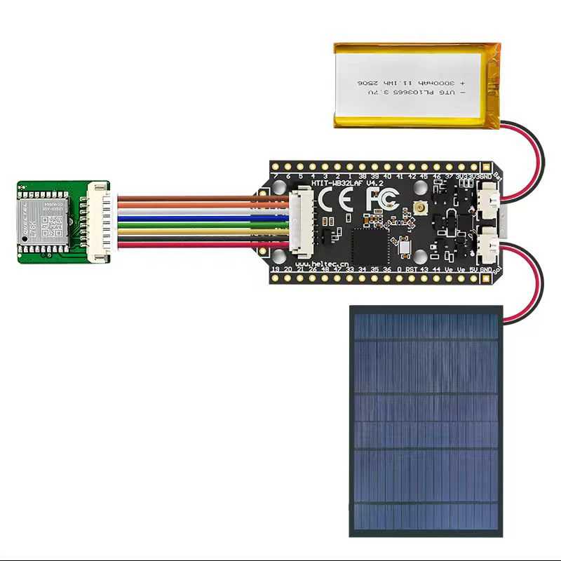
- Added SH1.25-2P solar panel interface.
- Optimized lithium battery management.
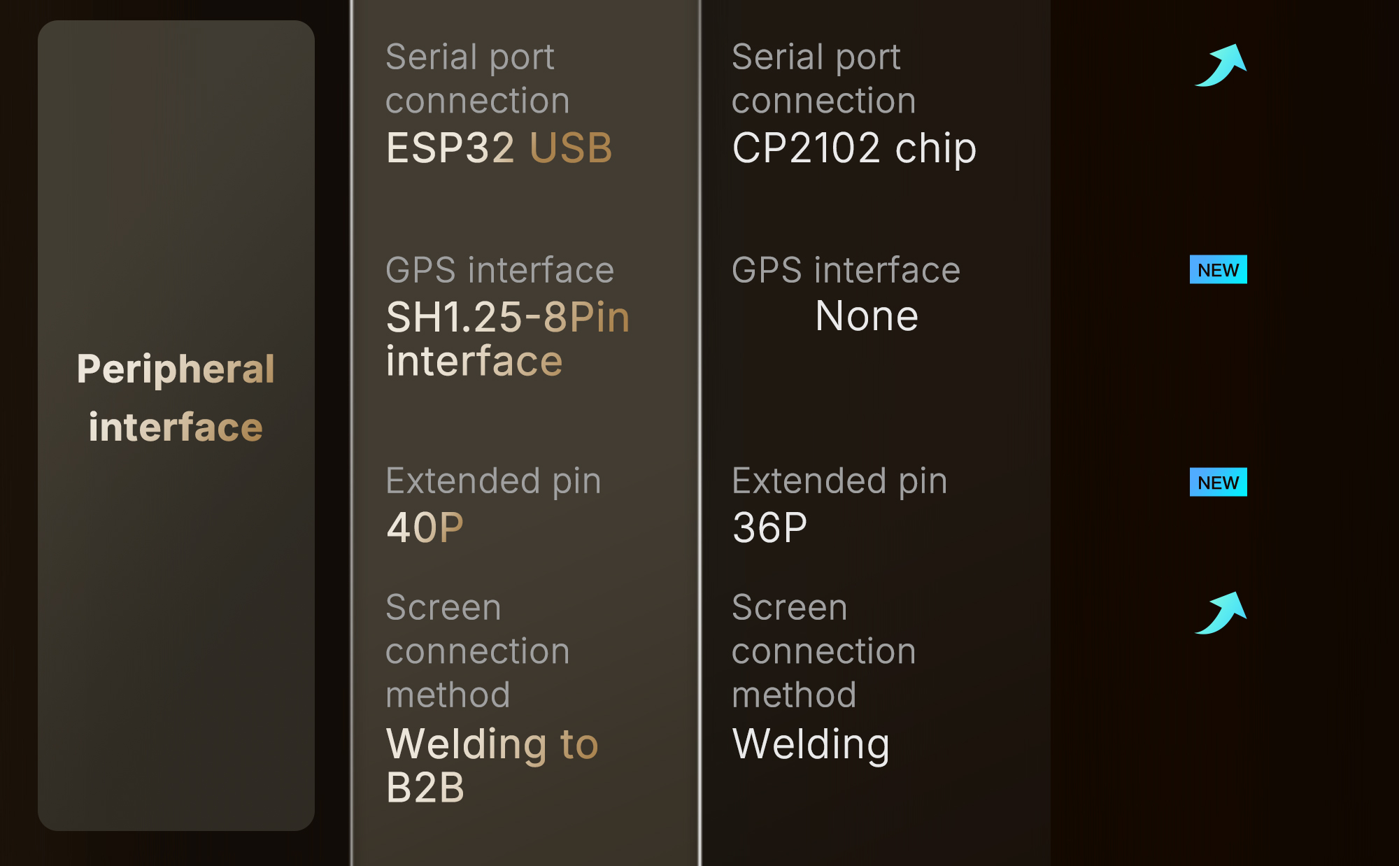
- Added SH1.25-8Pin GNSS interface.
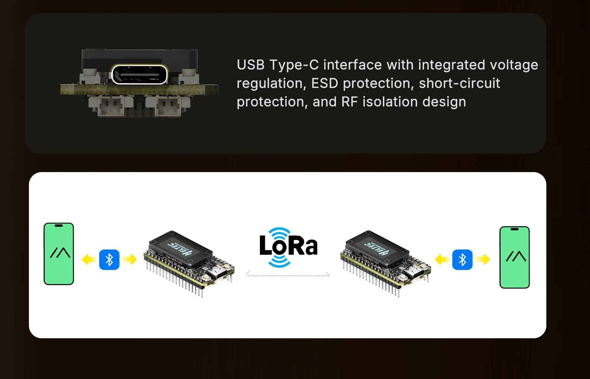
- USB Type-C interface with integrated voltage regulation, ESD protection, short-circuit protection, and RF isolation design.
- Low power consumption is less than 20 μA.
Compared to WiFi LoRa 32 V3, the V4 has made the following upgrades:
Docs & Resources
- User manual: https://docs.heltec.org/en/node/esp32/wifi_lora_32/index.html
- Heltec ESP (ESP32 & ESP8266) framework: https://github.com/Heltec-Aaron-Lee/WiFi_Kit_series
- Heltec ESP32 library: https://github.com/HelTecAutomation/Heltec_ESP32
- Schematic diagram: https://resource.heltec.cn/download/WiFi_LoRa_32_V4/Schematic
- Downloadable resource: https://resource.heltec.cn/download/WiFi_LoRa_32_V4
Pin Map
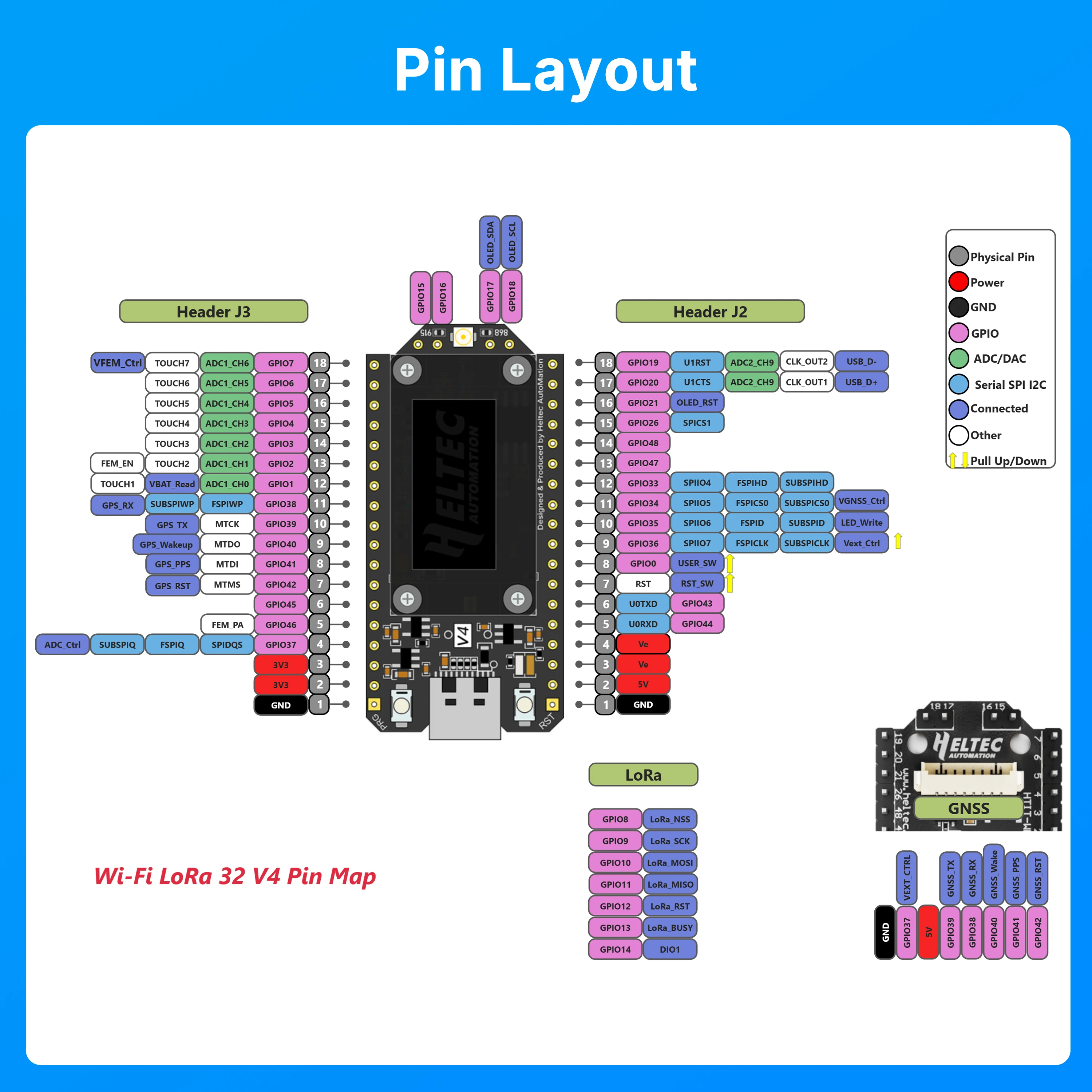
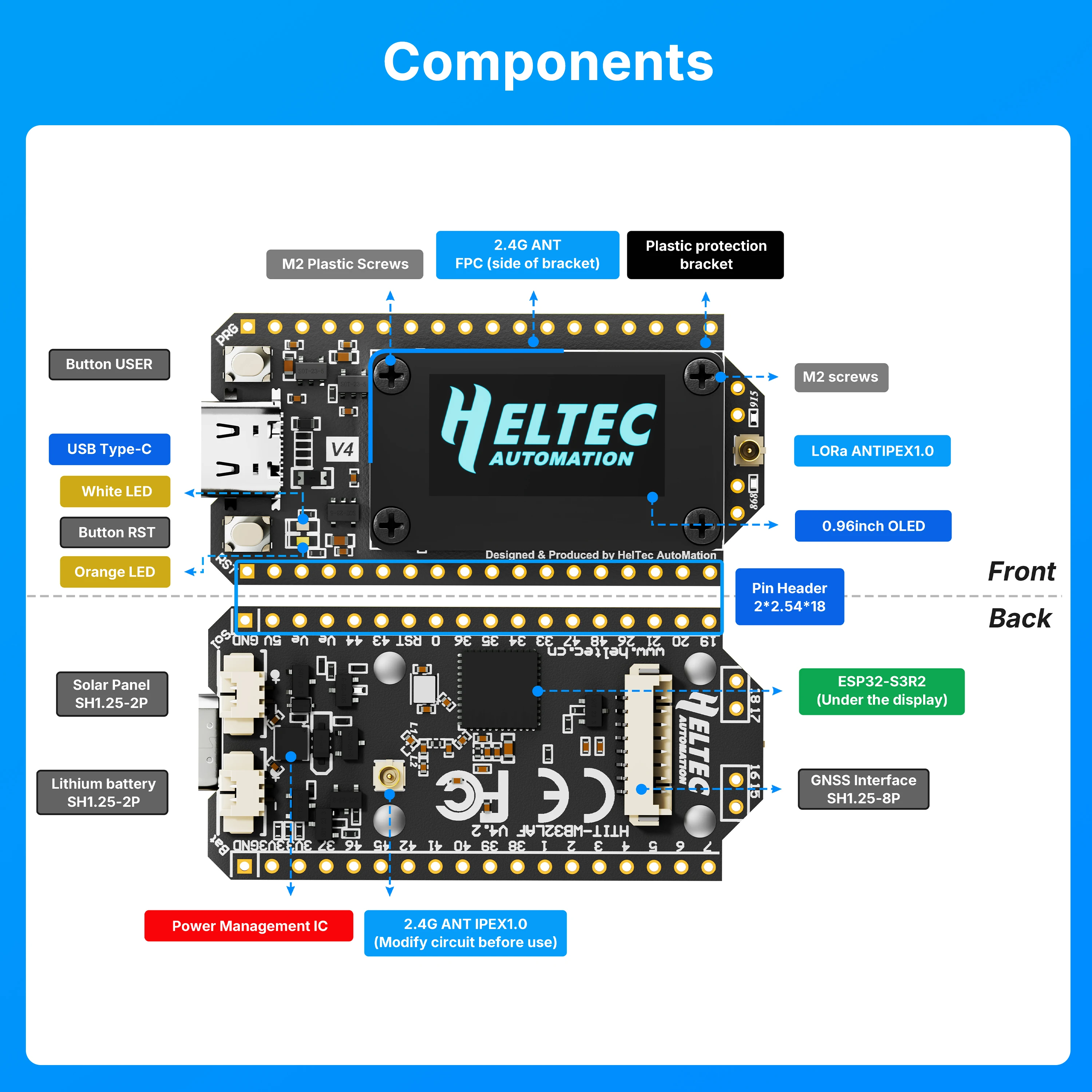
Specifications
| Parameters | Description |
|---|---|
| MCU | ESP32-S3R2 (Xtensa® 32-bit lx7 dual core processor) |
| LoRa Node Chip | SX1262 |
| Frequency | High-power version: 863-928MHz Low-power version: 433, 470-510MHz |
| Max. TX Power | High-power version: 28 ± 1 dBm Low-power version: 21 ± 1 dBm |
| Max. Receiving Sensitivity | -137dBm@SF12 BW=125KHz |
| Wi-Fi | 802.11 b/g/n, up to 150Mbps |
| Bluetooth | Bluetooth (LE), Bluetooth 5, Bluetooth Mesh |
| Hardware Resource | 7*ADC1 + 2*ADC2; 7*Touch; 3*UART; 2*I2C; 2*SPI; etc. |
| Memory | 384KB ROM; 512KB SRAM; 16KB RTC SRAM; 2MB PSRAM; 16MB Flash |
| Interface | Type-C USB; SH1.25*2 Pin lithium battery interface; SH1.25*8 Pin interface; LoRa ANT(IPEX1.0); 2.4G ANT(IPEX1.0) |
| Battery Applicable | 3.3-4.4V lithium battery |
| Operating Temperature | -20 ~ 70 °C |
| Dimensions | 51.7 * 25.4 * 10.7mm |
Packing List
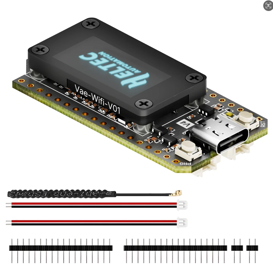
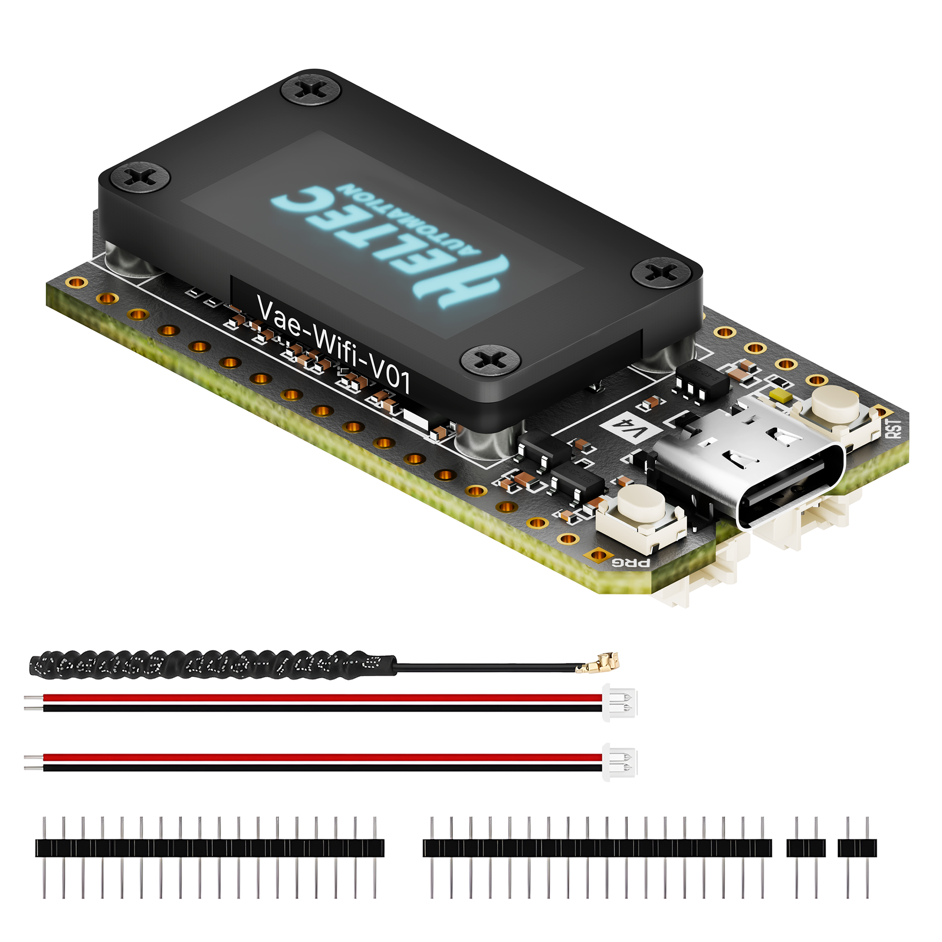
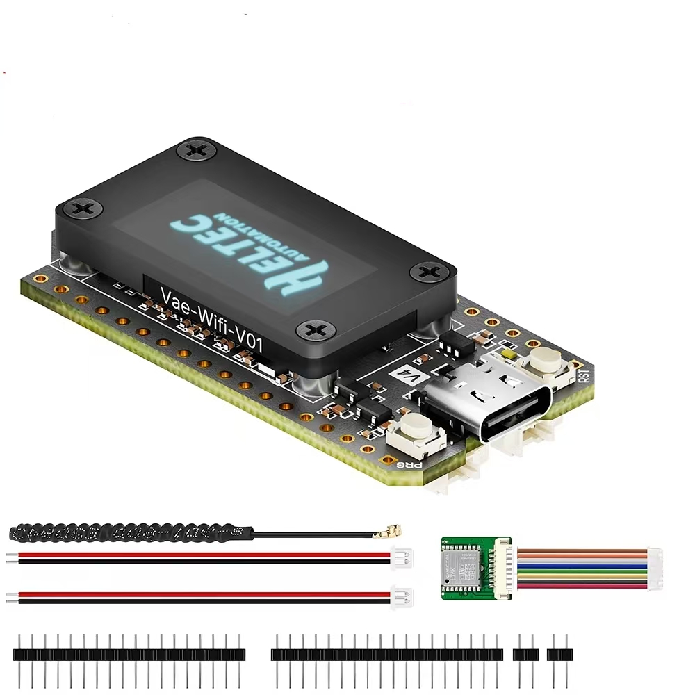
The default packing list without selecting any accessories is as follows:
1. Standard configuration (with spring antenna)
2. Standard configuration + GPS module (with spring antenna)
FAQ
Q1: 2.4GHz Antenna
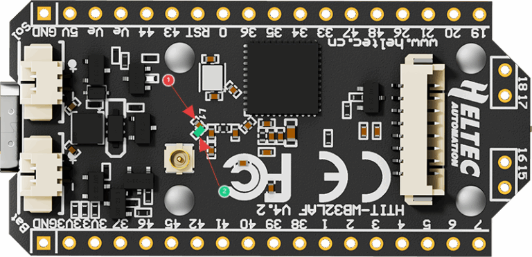
A1: The default 2.4G FPC antenna is located on the side of the plastic screen bracket.
If you wish to use an IPEX-connected 2.4G antenna, you need to remove the inductor marked as ① in the diagram below, and add a 0-ohm resistor (or other conductive metal or cable) at the position marked ② to connect to the IPEX interface.
Q2: What development methods does it support?
A2:
- Arduino
- MicroPython
- Platform.io
- Espressif IDE
We strongly recommend using Arduino. We have complete technical support and provide complete LoRaWAN code for the ESP32 Arduino framework.
Q3: What’s the battery socket type?
A3: You can find this type of socket by searching “SH1.25 x 2”.
Q4: Can I order a version without the OLED display?
A4: Of course, you can contact our sales staff and provide your ideas.
Q5: Are V3 and V4 compatible?
A5: They are compatible in most scenarios.
Since V4 uses the same series of chips as V3, features the same OLED, and has an almost identical pin layout, V3 and V4 can be used interchangeably in the majority of cases.
However, due to the increased transmit power, the transmit power settings in some code may no longer correspond directly to the actual output.
Q6: Failed to upload code
A6: Please try the following steps:
- Try using a different USB cable.
- Enter BootLoader mode. There are two methods to enter this mode:
- Hold down the PRG button, connect the USB-C cable, then release the PRG button.
- Connect the USB-C cable, hold down the PRG button, press the RST button once, then release the PRG button.
Related Products

🆕 Check Out Our Newest Arrivals – Fresh & Trending!
🛍️ Exclusive & Exquisite – Shop High-End Picks
Trending Categories